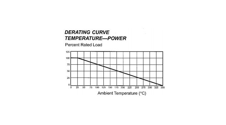
The power rating for resistors is generally specified at 25 degrees C (ambient) and it is important to understand when designing circuitry that a derating factor applies as temperature increases. For example, the precision wound series of resistors derate to 75 percent of their rated load at 100 degrees C and 50 percent at 175 degrees C. This can be an important consideration in some industrial applications where equipment housing these resistors may be located in areas (like blast furnaces, for example) that experience high ambient temperatures. If this is the case, a higher wattage resistor may be more appropriate than the initial power calculations suggest. Most resistor data sheets specify the temperature range that the resistors will operate under. For wire wound resistors this is typically -55C to +275 C, but varies depending on the physical construction of the resistor, its coating material and surface area. Ratings are generally specified ‘suspended in free air’ and taking into account the effect of any enclosing structure around the resistor assembly is an additional factor you should consider when determining power rating selection. The linearity of the derating is typically quite linear for wire wound resistors as is shown on the derating graph for the precision wound resistor range.
Resistor Coatings And Derating
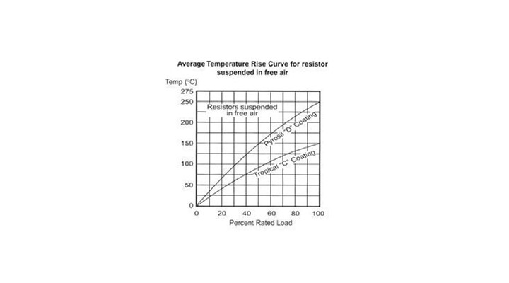
Many tubular wire wound resistors are manufactured by applying a resistance winding onto a tubular ceramic former (as is the case with the power wire wound resistor range). A coating material is then applied (generally several coats) to the resistor which effectively ‘seals’ the completed assembly and ensures long term reliable operation in high humidity environments and the mechanical integrity of the structure. Coating materials are generally silicon based and have been used in this application for many years with long term reliability. Different coating materials applied to the resistors have different effects on the temperature derating factor of the resistor. Different coatings can exhibit as much as a 50% reduction in specified power ratings.
Maximum Voltage Across Resistor Rating
This can be an important factor when selecting the most appropriate resistor for a particular application particularly where high voltages are concerned. The maximum voltage across a resistor is calculated a the square root of the rated wattage of the resistor, multiplied by its resistance value.
Example: 33 ohm, 100 watt power resistor. The maximum voltage across this resistor would be calculated as follows: √( 33 x 100) = 57 volts.
Power Rating
The power rating of a resistor is calculated as the square of the current multiplied by the resistance. (I ² x R , where I=current and R=Resistance). As discussed above, factors including temperature rating and maximum withstand voltage need to be considered when determining the correct power rating of a resistor for a specific application.
Termination Onto Power Resistors and Mounting Considerations
Because of the nature of construction of wire wound resistors, the electrical connection onto the resistor assembly can be an important consideration to ensure:
- Ease of assembly into the finished product
- Long term electrical reliability of the equipment
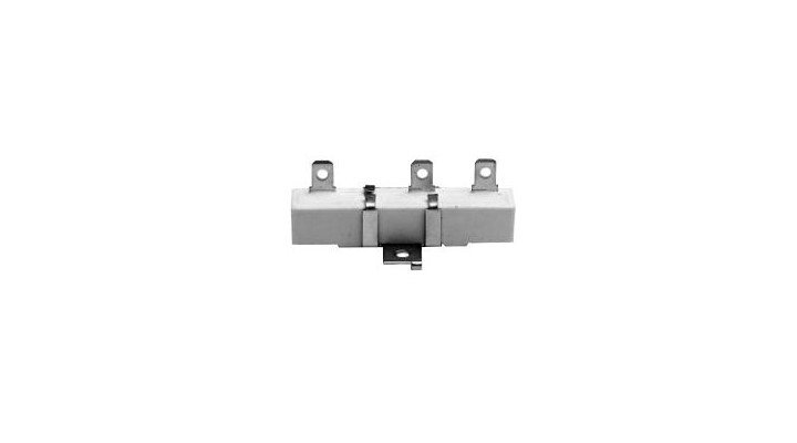
- Mechanical mounting considerations. For example some resistor assemblies are designed for ‘snap fit’ ferrule mounting
Methods of termination onto the resistor assemblies can include:
- Quick connect terminals employing standard 6.3mm spade lugs
- Flying leads
- Edison base – allowing for ‘screw in’ termination
- Nut and bolt through terminal termination
- Solder terminals
Mounting Of Resistor Assemblies
Given that large power resistors can be substantial in size, for example the YM series 1000 watt resistor has an ceramic length of 475mm, mounting considerations, ensuring mechanical integrity and air flow around the resistor are important issues. Mounting methods can include:
- Threaded rod mount with lock nuts to ensure rigidity and security of large mass power resistorsMounting ‘feet’ for tubular ceramic wire wound resistors. Plated metal mounting feet inserted into the ceramic former make for ease of mounting.
- Ceramic ‘boat’ style resistors can have a variety of mounting options including standard and custom brackets mounted to the ceramic body of the resistor. The brackets can allow for both horizontal and vertical mounting of the resistor assembly as shown below:
- vertical mount power resistor
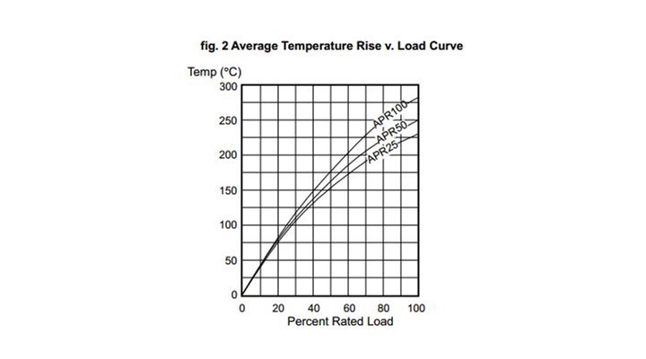
Average Temperature Rise Versus Load
Understanding the relationship between resistor surface temperature (and hence radiated heat) versus the percentage of rated load is important as it can be helpful in the specification and selection of the most appropriate resistor and in its temperature performance in the finished product.










-205x205.jpg)
-205x205.jpg)
